
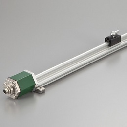
This is the linear profile version of GYSE-R.
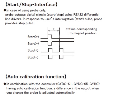
Between probe and controller, RS-422 differential line driver
transmission, providing robustness against electrical noise, is used.
In combination with a digital output controller, Min.1μm resolution is
possible.
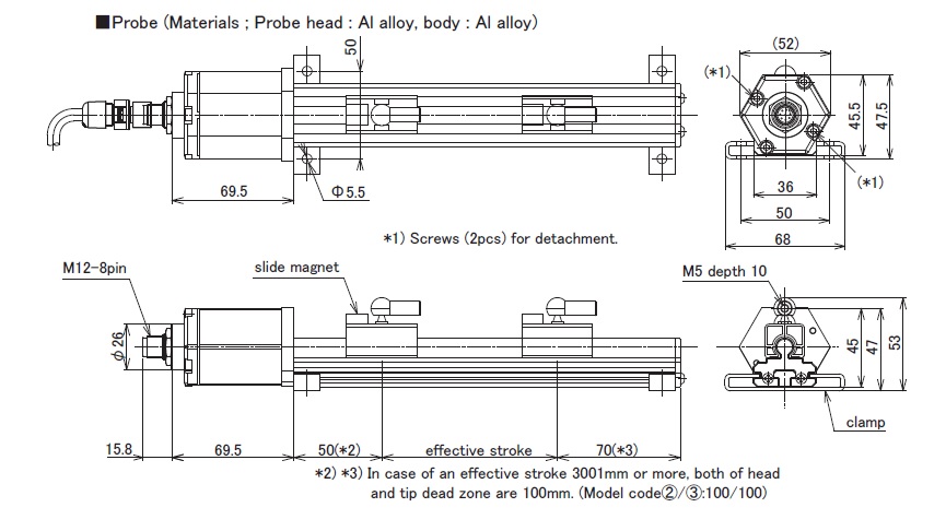
The inside probe elementcan be detached from the outer housing.
And by auto calibration function, a difference in the output when you
change the probe is adjusted automatically.
◆Associated controller
・Analogue output: GYHC(page 98)
・Digital output: GYDC-S1(page 102), GYDC-05(page 104)
・IRDS-GY (page 109) : When using the IRDM, you can connect with
CC-Link, CC-Link IE Field, PROFIBUS, EtherNet/IP, and EtherCAT.
・DC-Q (page 108) : MELSEC-Q built-in unit(page 106)
( Created on Dec. 4. 2025 )
| Non-linearity | ≦±0.025%FS Typ. |
|---|---|
| Resolution | (Analogue) 16bit (Digital) Min. 1μm |
| Repeatability | ≦±0.001%FS |
| Temp. drift | ≦±20ppmFS/°C |
| Operating temp. | -20°C〜+75°C |
| Storage temp. | -40°C〜+75°C |
| Vibration | 15G ( 10〜2000Hz ) |
| Shock | 100G ( 2msec ) |
| IP grade | IP65 |
・The above mentioned accuracy applies to sensors with an effective stroke of 300mm or more.
・The specification of stroke less than 300mm is equal that of stroke 300mm.
・Fixing clamps are supplied.(One clamp is added every 500mm)
stroke < 600mm:2 pcs
600-1000mm:3 pcs
1001-1500mm:4 pcs
1501-2000mm:5 pcs
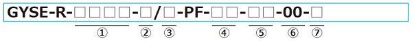
① Effective stroke
15mm〜7500mm
② Head dead zone
50 : 50mm (Std.)
□ : □mm (option)(specified by customers)
・Possible Min. length depends on the selected magnet.
③ Tip dead zone
70 : 70mm(Std.)
□ : □mm (option)(specified by customers)
・Possible Min. length depends on the selected magnet.
④ Associated magnet
PFU : PFU slide magnet
FE : No.5N-UK
BP : No.5PFT-LG
M11N : No.11N
M11S : No.11S
・Please consult if you select a magnet of other than above.
・This Model code means only specifying associated magnet.
・Ordering magnet individually.
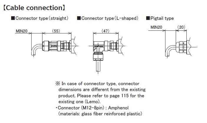
⑤ Cable connection
8P : connector(M12-8pin)
△G□F : pigtail / cable end : free
△G□A : pigtail / cable end : with connector for relay
(□:cable length(m)、Max.10m)(*)
(△:cable type
S:standard, H:high temp. cable, R:robot cable, UL : cUL cable)
CN : existing connector (Please refer to page 115 of option.)
(*) In case of using extension cable sensor cable (m) + extension cable (m) ≦ 200m
・Please confirm extension cable on page 120〜122.
・Ordering loose mating connector individually.
⑥ Output
00:depends on external controller
⑦ Clamp
F50 :with fixing clamps
N :without fixing clamps
・ Standard pcs (depend on stroke) of the clamp are applied.
Possible to order extra pcs individually.
・ Please refer to page 118 for clamp drawings.
| Probe | Cable connection | Cable | ||||
|---|---|---|---|---|---|---|
 |  |  | ||||