
GYHC controller outputs 0〜10V or 4〜20mA for position and ±10V
(or 4〜20mA) for velocity.
Using digital process inside, fine resolution is possible (1/65536).
With option, putting 2 pcs magnets on one probe and detecting
each magnet position or relative distance between 2 magnets
are possible.
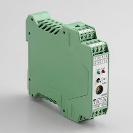
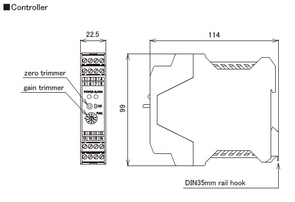
It has toggle switches on front face for zero/gain adjustment,
mounting with DIN rail.
With the captive software (GPM), zero and gain adjustment is
possible at user side.
・ CE marking
・ Noise cancellation
・ GPM setting
◆Auto-calibration
In combination with the probe (GYMR6, GYSE-R, GYKMR,
GYRHP-MR6) having auto calibration function, a difference in
the output when you change the probe is adjusted automatically.
( Created on Dec. 4.2025 )
| Resolution (position) | 16bit (1/65536) (*1) ≦0.01%FS (*2) |
|---|---|
| Position (OUT1) (OUT2 : option) | 0〜10V (Max.5mA, Min.2kΩ) or 4〜20mA (load :Max.500Ω) |
| Velocity(OUT2) (option) | ±10V or 4〜20mA |
| Alarm (*3) | Open collector 0.1A 30VDC (*3) |
| Power supply | Std. : +24VDC±5% (≦150mA) (*4) Option : +15VDC±5% (≦250mA) |
| Sampling freq. (*5) | Std. 1kHz (Total rod length : 1300mm) |
| Temp. drift | ≦±10ppmFS / °C |
| Operating temp. | 0°C〜+65°C |
| Storage temp. | -20°C〜+85°C |
・The above mentioned accuracy applies to sensors with an effective stroke of 300mm or more.
・The specification of stroke less than 300mm is equal that of stroke 300mm.
(*1) associated probe :GYMR6, GYSE-R, GYcRS, GYMR5, GYFRS, GYKMR, GYRHP-MR6, EX-GYdT-RS
(*2) associated probe :GYMS, GYGS, GYPM, GYPE2K, GYPMR, GYcRP, GYHTR, GYHR, EX-GYdS-RP, IGY4
(*3) Cable disconnection and magnet missing.
(*4) In case of adding analogue output ⑥, the consumption current is 170mA.
(*5) Sampling frequency is Max. 3.75kHz. It depends on the total rod length (model⑧),
and the consumption current increases.

① Probe
MR6 : GYMR6
SR : GYSE-R
RS : GYcRS
RP : GYcRP
R5 : GYMR5
FS : GYFRS
HTR : GYHTR
HR24 : GYHR
MS : GYMS
GS : GYGS
PM : GYPM
P2 : GYPE2K
RR : GYPMR
KMR : GYKMR
PMR6 : GYRHP-MR6
ETS : EX-GYdT-R
ESP : EX-GYdS-R
I4 : IGY4
② Effective stroke (mm)
③ Head dead zone
□ :□ mm (option) (specified by customers)
| magnet | float |
|---|---|
| MG0:No.Φ M0SM:No.ΦSPM M0LM:No.ΦLPM M2P:No.2P M2PN:No.2PN M3:No.3 M11:No.11 M11N:No.11N T142:No.T14-M2 T144:No.T14-M4 T162:No.T16-M2 T163:No.T16-M3 BA:No.2KYN-17-LG | F28S:Φ28SUS316L F30S:Φ30SUS316L F40S:Φ40SUS316(B) F42S:Φ43SUS316L F50S:Φ50SUS316L F54S:Φ54SUS304 F25N:RF-A10 plastic F28N:RF-A6 plastic |
・Same as the selected magnet or float of probe.
・Please consult our factory in case of requesting special magnet or float.
・This model code means only specifying associated magnet or float.
・Ordering magnet or float individually.
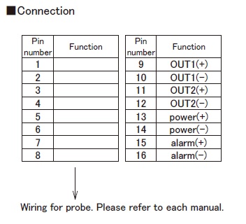
⑤ Position output (OUT1)
AD :0〜10V ( When magnet moves toward tip, output increase )
AR :10〜0V ( When magnet moves toward tip, output decrease )
BD :4〜20mA ( When magnet moves toward tip, output increase )
BR :20〜4mA ( When magnet moves toward tip, output decrease )
CD□□ :bipolar output (-□V〜+□V)
(for example CD10 :-10V〜+10V)
CR□□ :bipolar output(+□V〜-□V)
(for example CR05 :+5V〜-5V)
V Z/F :option (specified voltage)
(for example V1/5 :1〜5V, V9.5/0.5:9.5〜0.5V)
I Z/F :option (specified current)
(for example I5.2/20 :5.2〜20mA, I18/5 :18〜5mA)
【 Z=output at zero position, F=output at full position 】
⑥ Option : Analogue output (OUT2)
・N :without option (Std.)
・Position output :select from ⑤
・Velocity output (Note1)
VA[ ] :±10V
WB[ ] :4〜20mA
[ ] :max velocity (1.00〜999mm/sec) (ex.9R99: max velocity=9.99mm/sec)
(Note1)
VA :When magnet stops, output is 0V. When moving toward probe tip, +10V.
WB :When magnet stops, output is 4mA. When moving in any direction, 20mA.
⑦ Power supply
24S:+24VDC(Std.)
15S:+15VDC(option)
12S:+12VDC(option)
15W:±15VDC(option)
* Power supply voltage and current consumption
+24VDC±2V(≦150mA)
+15VDC +2V,-5V (≦240mA)
+12VDC +5V, -2V (≦300mA)
±15VDC±2V (+15V:≦150mA, -15V:≦150mA)
⑧ Option
2ME:2 magnets, each magnet position (analog output)(*)
2MR:2 magnets, relative distance between the two.(*)
( OUT1 only, analog output )
X2:2kHz sampling (total rod length : Max. 700mm)
X3:3kHz sampling (total rod length : Max. 500mm)
X4:3.75kHz sampling (total rod length : Max. 400mm)
HS:resin coating against humidity
(*) 2 magnets option
・ Min. proximity distance between magnets is 75mm.
( Min. proximity distance between magnets varies depending on the magnet type.)
・ When using other magnets, please consult our factory.
| Controller | Connection | |||||
|---|---|---|---|---|---|---|
 |  | |||||