
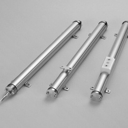
GYKMR is replacement model of GYKM-RS which head part
became slim.
And it was added auto calibrationfunction.
By the function, a difference in the output when you change
the probe is adjusted automatically.
◆Associated controller
・Analogue output : GYHC (page 98)
・Digital output : GYDC-S1 (page 100), GYDC-05 (page 104)
・IRDS-GY (page 109) : When using the IRDM, you can connect with
CC-Link, CC-Link IE Field, PROFIBUS, EtherNet/IP, and EtherCAT.
・DC-Q (page 108) : MELSEC-Q built-in unit(page 106)
( Created on Dec.4. 2025 )
| Non-linearity | ≦±0.025%FS Typ. |
|---|---|
| Resolution | (Analogue) 16bit (Digital) Min. 1μm |
| Repeatability | ≦±0.01%FS |
| Temp. drift | ≦±20ppmFS/°C |
| Operating temp. | 0°C〜+65°C |
| Storage temp. | -20°C〜+65°C |
| Vibration | 3G ( or 40Hz 2mmPP ) |
| Shock | 10G ( 2msec ) |
| IP grade | IP53, IP64, IP65 |
・The above mentioned accuracy applies to sensors with an effective stroke of 300mm or more.
・The specification of stroke less than 300mm is equal that of stroke 300mm.
・Resolution depends on associated controller.
・Mounting brackets (fixing clamps) are supplied.
stroke < 600mm : 4 pcs (2 pcs)
600〜1000mm : 6 pcs (3 pcs)
1001〜1500mm : 8 pcs (4 pcs)
1501〜2000mm :10 pcs (5 pcs)
2001〜2500mm :12pcs (6 pcs)

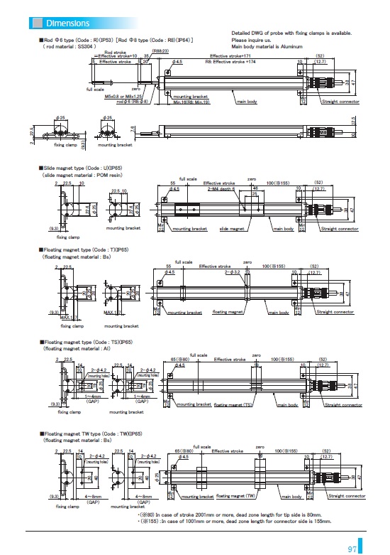
① Effective stroke
15mm〜2000mm (rod type, T, TW, U)
15mm〜500mm (both end universal joint types)
15mm〜2500mm (TS)
② Magnet
R: rod Φ6 (M5 thread)(Standard)
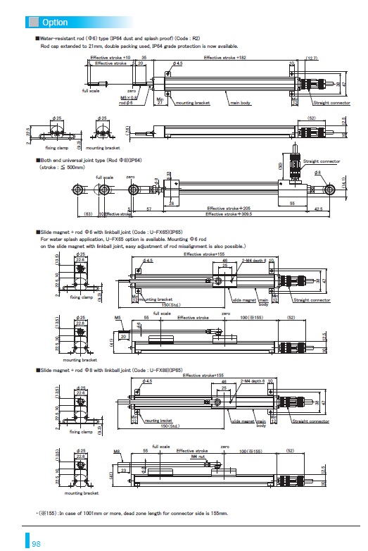
R2: rod Φ6 (M5 thread)
R88: rod Φ8 (M8 thread)
R85: rod Φ8 (M5 thread)
RW88: Both end universal joint type (rod Φ8)<IP64>
U: Slide magnet
T: Floating magnet (gap 1mm)
TS: Floating magnet (gap 4mm)
TW: Floating magnet (gap 8mm)
U-FX65 :Slide magnet + rod Φ6 (M5 thread) with linkball joint
U-FX88 :Slide magnet + rod Φ8 (M8 thread) with linkball joint
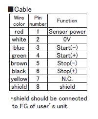
③ Cable connection
8P : connector type (M12-8pin)
△G□F: pigtail / cable end : free
△G□A: pigtail / cable end : with connector for relay
(□: cable length (m)、Max.10m)(*)
(△: cable type
S:standard, H:high temp. cable, R:robot cable, UL : cUL cable)
(*)In case of using extension cable, sensor cable (m) + extension cable (m) ≦ 200m
・Please confirm extension cable on page 120〜122.
④ Output
00 :depends on external controller
⑤ Dead zone
In case of an effective stroke 2001mm or more for floating magnet TS,
dead zone length for tip side is 80mm (Std. length 65mm + 15mm).
Model code of dead zone will be the actual length (mm).
・S/S : Std.
・S/80 : 2001mm〜(TS type)
⑥ Clamp
K38 : with mounting brackets
F50 : with fixing clamps
N : without mounting brackets and fixing clamps
・The number of pieces included is determined by the stroke.
If you need more than that, please specify separately.
・Please refer to page 118 for clamp drawings.
| Dimensions | Dimension (Option) | Cable | ||||
|---|---|---|---|---|---|---|
 |  |  | ||||