
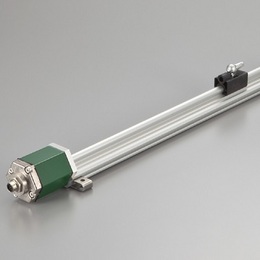
This is the linear profile version of GYSE-S.
GYSE-S probe outputs displacement of the magnet as SSI
(Synchronous Serial Interface).
SSI is output of a serial communication-type and outputs the position
data of 24 - 27 bit.
When using SSPC-03 of separate sale, you can convert SSI to parallel
data.
So you can get the data in the I/O unit.
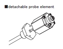
The inside probe element can be detached from the outer housing,
and with the captive software (GPM), zero and gain adjustment is
possible at user side.
・ CE marking
・ Noise cancellation
・ GPM setting
( Created on Nov, 21. 2025 )
| Non-linearity | ≦±0.025%FS Typ. |
|---|---|
| Resolution | 0.1mm〜0.001mm specified |
| Repeatability | ≦±0.001%FS (Min.±3μm) |
| Temp. drift | ≦±15ppmFS /°C |
| Position (Std.) | SSI (Synchronized Serial Interface), 24〜27bit, Binary(Std.) or Gray |
| Velocity (Option) | Not available |
| Alarm | Open drain 50V 0.1A ( for magnet missing ) |
| Power supply | DC24V(±2V) 70mA |
| Sampling freq. (*) | Std. 1kHz ( Total body length : 1300mm ) |
| Operating temp. | -20°C〜+75°C |
| Storage temp. | -40°C〜+75°C |
| Vibration | 15G ( 20〜100Hz ) |
| Shock | 100G ( 2msec ) |
| IP grade | IP65 |
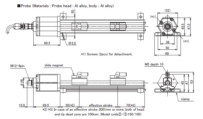
・The above mentioned accuracy applies to sensors with an effective stroke of 300mm or more.
・The specification of stroke less than 300mm is equal that of stroke 300mm.
(*) Sampling frequency : Max. 3.75kHz
(It depends on the total body length (shows in Model ⑫), and the consumption current increases. )
・Fixing clamps are supplied. (One clamp is added every 500mm)
stroke < 600mm:2 pcs
600-1000mm:3 pcs
1001-1500mm:4 pcs
1501-2000mm:5 pcs
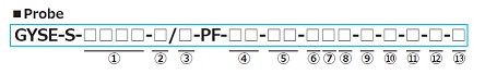
① Effective stroke
15〜7500mm
② Head dead zone
50 :50mm (Std.)
□ :□mm ( option ) ( specified by customers )
・Possible Min. length depends on the selected magnet or float.
③ Tip dead zone
70 :70mm(Std.)
□ :□mm ( option ) ( specified by customers )
・Possible Min. length depends on the selected magnet or float.
④ Associated magnet
PFU :PFU slide magnet
FE :No.5N-UK
BP :No.5PFT-LG
M11N : No.11N
M11S : No.11S
・Please consult our factory in case of requesting special magnet.
・This model code means only specifying associated magnet.
・Ordering magnet individually
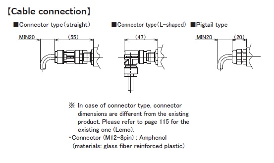
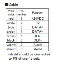
⑤ Cable connection
8P:connector (M12-8pin)
△G□F:pigtail / cable end : free
△G□A:pigtail / cable end : with connector for relay
(□:cable length(m)、Max.10m)(*)
(△:cable type
S:standard, H:high temp. cable, R:robot cable, UL : cUL cable)
CN:existing connector (Please refer to page 115 of option,)
(*)In case of cable 10m or more, please use extension cable.
・Please confirm extension cable on page 120-122.
・Ordering loose mating connector individually.
⑥ Resolution
D2:0.1mm
D3:0.05mm
D4:0.01mm(Std.)
D5:0.005mm
D7:0.002mm
D8:0.001mm
DF:0.5μm
DG:0.2μm
DH:0.1μm
⑦ Linearity option
blank: without option
L : Linearization option (at room temperature)
⑧ Direction
D:When magnet moves toward tip, output increase
R:When magnet moves toward tip, output decrease
⑨ Number of bits
4:24bit (Std.)
5:25bit
6:26bit
7:27bit
⑩ Output code
B:Binary(Std.)
G:Gray
⑪ Synchronous
5A:asynchronous SSI
5S:synchronous SSI
⑫ Option
blank : without option
SRT : SRT option (Recommendation:pigtail type)
Please confirm the details of SRT option on page 114.
High-frequency sampling:
Only when "5A (asynchronous)" is selected in ⑪.
X2:2kHz sampling (total rod length : Max.700mm)
X3:3kHz sampling (total rod length : Max.500mm)
X4:3.75kHz sampling (total rod length : Max.400mm)
⑬ Clamp
F50:with fixing clamps
N:without fixing clamps
・ Standard pcs (depend on stroke) of the clamp are supplied.
Possible to order extra pcs individually.
・ Please refer to page 118 for clamp drawings.
| Probe | Cable connection | Cable | Detachable probe element | |||
|---|---|---|---|---|---|---|
 |  |  |  | |||