
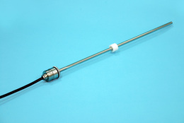
GYPD probe is the sensor for built-in hydraulic cylinder
which has analogue output.
The sensor head is compact and the head dead zone is also short,
so its total length becomes space saving.
With the dedicated software (GPM), zero and gain adjustment is
possible at the user.
Output methods from sensors include analog (voltage/current) and
PWM, CANopen methods.
We have also developed the SEA J1939 method as a new product.
Please contact us if you would like to use the SEA J1939 method.
( Created on Nov.20. 2025 )
| Non-linearity | ≦±0.1mm(30〜250mm) ≦±0.04%FS(≧251mm) |
|---|---|
| Resolution | ≦0.06mm *CANopen:≦0.1mm |
| Repeatability | ≦±0.06mm *CANopen:≦±0.1mm |
| Temp.drift | ≦±0.006%FS/°C |
| Voltage output | 0.25〜4.75V or 0.5〜4.5V (load : Min.2kΩ) |
| Current output | 4〜20mA ( load : Max.250Ω ) |
| PWM output | 1kHz 5V 95〜5% ( load : Min.5kΩ ) |
| CANopen | CiA-301 ver. 4.2 / CiA-305 ver. 3.0.0 / CiA-406 ver. 4.2 |
| Power supply | +8〜36VDC (≦0.8W) |
| Sampling frequency | 4kHz (≦250mm) 2kHz (251〜500mm) 1kHz (≧501mm) |
| Max. Pressure | 45MPa ( continuous operating pressure ) |
| Operating temp. | -20°C〜+85°C |
| Storage temp. | -20°C〜+85°C |
| Vibration | 20G ( 5 〜 2000Hz ) |
| Shock | 100G ( 2msec ) |
| IP grade | IP67 |
(*): Changed the values for CANopen output. (20230208)
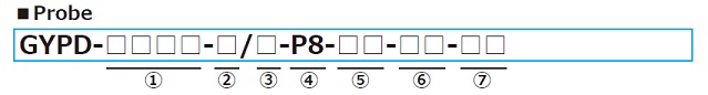
① Effective stroke
30mm-1000mm
② Head dead zone
15 : 15mm (Std.)
□ : □mm (option) ( specified by customers )
・Possible Min. length depends on the selected magnet.
③ Tip dead zone
70 : 70mm (Std.)
□ : □mm (option) ( specified by customers )
・Possible Min. length depends on the selected magnet.
④ Mount / Rod diameter
P8 : O-ring, rod Φ8(Std.)
⑤ Associated magnet
< magnet >
M3 : No.3
M0SM : No.ΦSPM
・Please consult if you select a magnet of other than above.
・This Model code means only specifying associated magnet.
・Ordering magnet individually
⑥ Cable connection
RG□F : pigtail / cable end : free
RG□A : pigtail / cable end : with connector for relay
( □ : cable length(m), Max.10m )(*)
KV□△ : M12 receptacle type
□ : wire length (by 0.01m), Max.0.1m
△ : pin assignment( H: pin assignment "H", G: pin assignment "G",
FF: pin assignment "FF")
(*) In case of using extension cable
Voltage output : sensor cable(m) + extension cable(m) ≦ 10m
Current output : sensor cable(m) + extension cable(m) ≦ 100m
PWM output : sensor cable (m) + extension cable (m) ≦ 10m
⑦ Position output
A1 : 0.25-4.75V ( When magnet moves toward tip, output increase. )
A2 : 4.75-0.25V( When magnet moves toward tip, output decrease. )
A3 : 0.5-4.5V( When magnet moves toward tip, output increase. )
A4 : 4.5-0.5V( When magnet moves toward tip, output decrease. )
BD : 4-20mA( When magnet moves toward tip, output increase. )
BR : 20-4mA( When magnet moves toward tip, output decrease. )
PWM1 : 1kHz 5V(5-95%)
PWM2 : 1kHz 5V(95-5%)
CO : CANopen
| Probe | M12 receptacle | Application | ||||
|---|---|---|---|---|---|---|
 | ||||||